
DL-NIRSP uses the BiFOIS (Birefringent Fiber-Optic Image Slicer) technology to implement integral field spectropolarimetry. BiFOIS consists of an array of densely packed rectangular-cored fibers that transmit two orthogonal states of linear polarization. These fibers are reformmated into five slits for the grating spectrograph. DL-NIRSP will be equipped with two separate BiFOIS IFUs with different core sizes meaning different spatial samplings.
Using these BiFOIS IFUs, DL-NIRSP records the resolved spectra of multiple spectral features from a spatially-resolved two-dimensional field in a single exposure.
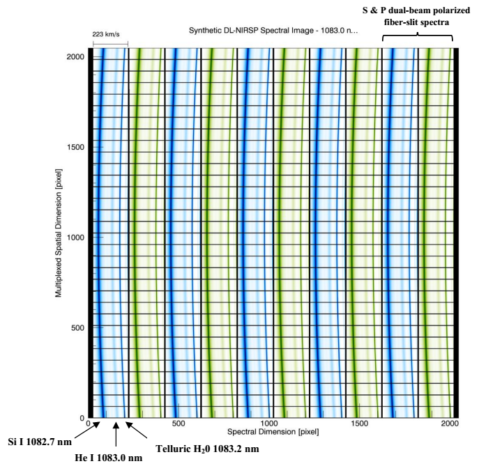
An example synthetic image of the DL-NIRSP focal plane is given below for a baseline infrared detector (2048 x 2048 pixels). Encoded within this single frame is the radiative intensity of the polarimetrically modulated spectra emerging from a two-dimensional spatial field, as sampled by the DL-NIRSP fiber-based integral field unit (IFU) spectrograph. The IFU reformats the 2D spatial field into 5 parallel slits, each of which in this case consists of 30 fiber ribbons. The ribbons are separated by 4 dark pixel rows. The figure depicts the He I 1083 nm spectral channel that also contains the Si I 1082.7 nm spectra line as well as the 1083.2 nm telluric water line. The blue and green spectra correspond to the S & P polarized beams used for dual-beam spectropolarimetry. Spectrograph slit curvature has been applied to the spectra.

Selectable spatial and spectral resolution modes are available to balance the available light flux with temporal resolution and the need for simultaneous field of view coverage.
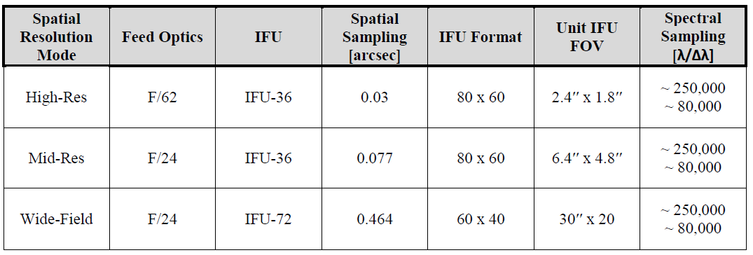
The DL-NIRSP optical design includes two different configurations of its feed optics and two different fiber-optic IFUs (integral field units). Together these configurations provide three different resolution modes available for observations. Options range from a high-resolution diffraction limited mode, to a middle-resolution mode that takes advantage of the high solar flux of the DKIST 4m primary to study dynamic magnetism, to finally a wide-field mode that captures the wide-field structure of active regions and off-limb phenomena.
The available spatial resolution modes are summarized below. The IFU format refers to the shape and number of spatial pixels encoded in a single DL-NIRSP exposure. Coupled with the selected feed optics, the unit IFU field-of-view denotes the effective field-of-view of this single exposure. By scanning the solar image across the IFU, a total field of view up to 120 x 120 arcseconds can be achieved.

DL-NIRSP spectral coverage is, under normal scenarios, 1/1250th of the wavelength being observed. In high resolution mode this is equivalent to 200 spectral samples per spatial pixel. Stated alternatively, this is 240 km/s of total velocity coverage for each observed spectral line. The full spectral coverage is recorded in every DL-NIRSP exposure.
At least two spectral sampling resolutions will be provided by DL-NIRSP. On-disk observing will requires high spectral resolution. A 23.3 ln/mm, 63 degree blaze reflection grating will provide sampling of R ~ 250000 for these observations.
Experiments requiring less spectral resolution will benefit from the use of a 7.9 ln/mm, 27 degree blaze grating that provides R ~ 80000 spectral sampling on the detector. The lowered sampling resolution boosts the flux incident on each detector pixel leading to better temporal resolution of the observations.
DL-NIRSP uses a very fast tip/tilt mirror to scan the solar image across the IFU spectrograph. This provides flexible, partial and/or complete field-of-view coverage (up to 120'' x 120''). For solar observations, an IFU spectrograph provides a considerable advantage when targeting features of a limited spatial extent. To put this in perspective, compare the DL-NIRSP spatial, spectral, and field coverage to other instrument types.
A single slit spectrograph records spectral images along a one spatial dimensional of some typically large extent. Building an image requires scanning this slit in time to sample the entire field of view needed in the direction parallel to the slit. The number of required exposures scales with the number of samples needed in the direction parallel to the slit.
A Fabry-Perot based imaging spectrograph typically has a large simultaneous field-of-view but must scan its etalon(s) to sample the spectral direction. The number of required exposures scales with the number of wavelength samples.
An IFU spectrograph, like DL-NIRSP, covers a simultaneous field-of-view equivalent to a comparable slit-based spectrograph but with a much different shape, i.e. over a continuous two-dimensional field. The number of required exposures scales with the number of samples in each dimension divided by the number of samples provided by a single field position of the IFU.
The DL-NIRSP spectrograph has three spectral relay arms for simultaneous measurements of up to three different spectral windows using three separate detectors. The wavelength range of each relay arm is defined below.
In principle, an arbitrary selection of three spectral lines (one in each of the wavelength bands) may be measured by DL-NIRSP. However, the DL-NIRSP spectrograph operates at high-order, meaning custom filters are required for most spectral lines. A limited library of filters will be available at commissioning that may be expanded over the lifetime of the instrument.

DL-NIRSP uses a combination of a single polychromatic modulator and Wollaston prisms to perform dual-beam full Stokes polarimetry with spatio-temporal modulation.
DL-NIRSP can be operated in parallel with VBI, VISP, and VTF, all while using the DKIST adaptive optics system.
Typically, the visible arm of DL-NIRSP will not be available during parallel observations with other DKIST instruments due to a low visible throughput to DL-NIRSP in this configuration.